Can you spot any difference between the two images below? The one on the left is from Fritzing version 0.4.2; the one on the right is from version 0.4.3.
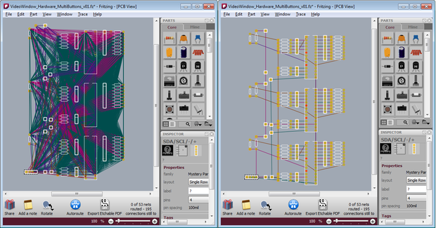
The difference is that in 0.4.2 a ratsnest displays every possible connection in a net. In 0.4.3 we show only one possible path–one set of connections–through the net.1 What is a ratsnest? If you already know, then feel free to skip ahead a couple of paragraphs.
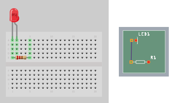
A ratsnest displays a set of connected connectors (a “net”), and it can suggest potential paths for routing between those connectors. In the simplest case, if you connect two parts (well, really two connectors) in breadboard view, a ratsnest in PCB view will show that those connectors are connected by drawing a line between them, and thereby suggest where you might draw a trace.This image displays a single net:
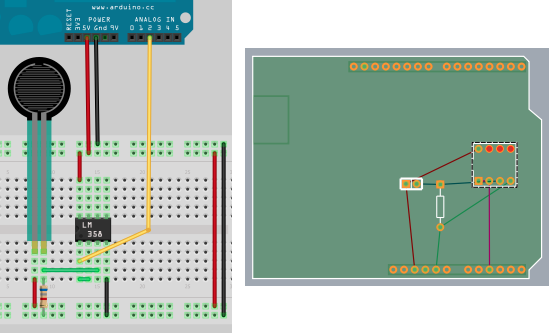
In a more complex case, we have multiple connectors connected, but not directly. Here, an individual ratsnest line can act as a “virtual wire”, drawing a line between two connectors that are electrically connected, but not directly wired to each other; for example, the connection between the resistor and the LM358. There are four nets in this image, as you can see from the four different ratsnest colors:
Starting with release 0.4.2 and continuing with 0.4.3, we have reimplemented ratsnests in Fritzing. The overall goal was to make them more useful–more like an interface widget than a wire–by adding functionality and improving their diagrammatic quality. In 0.4.2, we worked on the functionality, and added a couple of features:
- double-click a ratsnest to create a trace between its connectors
- delete a ratsnest to electrically isolate its connectors 2
With 0.4.3, we have concentrated on the diagramming–you can see the results in the initial pair of images above. Clearly PCB and schematic view are more readable, and better suggest where you might want to draw your traces. Another change is that in 0.4.2, as you drew traces between connectors, ratsnest lines would dim to let you know that that connection had been routed (directly or indirectly). In 0.4.3, routed ratsnest lines simply disappear (reappearing as necessary as traces are removed).
This leads us to another difference between 0.4.3 and prior versions: “jumper wires” are now obsolete. Their purpose was to show unrouted connections, which is what ratsnest lines are now doing. (Note that jumper items are not obsolete, just jumper wires–the former are basically a pair of connectors with nothing in-between, the latter was essentially a Fritzing UI construct).
There are two pleasant side-effects with the new approach. First, we no longer save ratsnests in sketch files, which means that Fritzing file sizes typically shrink anywhere from twenty to eighty percent. But do not tremble, your old Fritzing sketches are completely compatible with 0.4.3 (though the old ratsnest lines and jumper wires will be replaced by new ratsnest lines), and if you save the file back out, only its ratsnest and jumper wire elements will change. The second side-effect is that since the program is no longer keeping track of so many objects, there’s been a noticeable improvement in Fritzing performance. If any of you were driven to use the “speed hack” in Fritzing 0.4.2, Fritzing 0.4.3 is that fast, or faster.
Cheers,
PS. Thanks to Jim Bollensée and Olmo Claessens for permission to use their sketch to illustrate the changes.
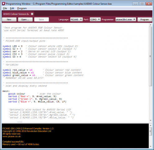
The latest release of Fritzing (0.4.0) has a surprise new experimental feature: a programming window. It’s intended to be a place to type your script for downloading to a microcontroller, and then actually download it. It’s not intended to replace your usual microcontroller programming environment. Rather, it’s meant to be a lightweight alternative, particularly useful for novices, workshops, and classrooms. It’s also a nice way to keep both your sketch and script files together.
At the moment, Fritzing only fully supports the PICAXE microcontroller, and only on the Windows platform. While there is support for typing in Ardiuno programs, we do not yet handle the download part (and that may have to wait for the release of Arduino 1.0).1
There is one programming window per sketch, but a programming window can have multiple tabs. The reason for multiple tabs is that we imagine you might want to play with slightly different versions of the same script until you hone in on one.
Aside from the standard file and edit commands, there are four steps you need to perform.
- First, choose the microcontroller language for your script. Right now there are two choices, Arduino and PICAXE.2 Once you choose a language, you will notice that the script you're working on is highlighted according to that language, and also that you can only save or load files with the appropriate extension.
- Second, select a serial port. First plug in your microcontroller into your USB port. This should create a new USB serial port for that device, which should now be listed when you click on the port combo box.
- Third, select a programmer (i.e. the executable which will compile and download your script). Fritzing does not install these programs for you, you have to do it yourself.
- Fourth, hit the program button. Feedback from the programmer should be displayed in the console area on the bottom of the programming window.
Here’s an image. As usual, we will be refining the implementation and UI in future releases.
A couple of acknowledgements. This work was partly sponsored by PICAXE (grateful thanks to Clive). And thanks to Bryant–our first new major code contributor–for co-implementing this feature.
That’s it, happy programming.
1. For the technically minded, here is the explanation: right now there’s not a simple way to invoke the Arduino compiler and downloader via shell command(s). This feature is slated for Arduino 1.0.
2. There are two requirements for adding a new language to the programming window. First, to enable syntax highlighting, Fritzing implements a subset of Kate Highlighting XML. So a new Kate Highlighting XML file has to be provided for each new microcontroller language. You can find the current set of highlighting files in your Fritzing installation folder, in the …/translations/syntax folder. The second requirement is to find a compiler/downloader for the microcontroller that can be accessed via shell commands.
One of the biggest and earliest requests for Fritzing was for it to handle double-sided (i.e. two-layer) boards. For those who don’t know, a two-layer board means you can route traces between connections on both the front and the back sides of the board, so compared to single-layer boards, this can save hand-wiring after etching, and the board will be more reliable.
We are pleased to announce that double-sided boards are supported in latest release of Fritzing (0.4.0). We tried to build in the minimal necessary functionality, and we’d like to hear your feedback about what’s still missing (and what’s buggy–we made a lot of changes from 0.3.19). For example, though Fritzing 0.4.0 supports wiring on both sides, it only supports adding parts to the top1 (which is what you do currently). If there’s a big demand for adding parts to the bottom, we will include this in a later release.
From a UI point-of-view, Fritzing is much the same. In fact, to work with single-sided boards, there is no change at all: just run Fritzing as usual. Your old sketches and parts will be fine. To switch into two-sided mode, go into PCB View, select your board, and in the Inspector palette, select “double-sided” in the combo box labeled “layers”. If you’re already working on a project and want to switch it to double-sided, don’t worry: changing the number of layers from 1 to 2 will not affect any connections2.
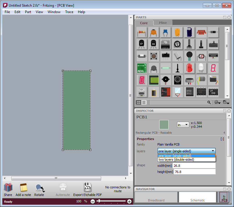
- Figure 1. Using the inspector to change the number of board layers
The way Fritzing models it, in PCB View you’re looking down at the top of the board. Through-hole parts (i.e. most of the parts that are currently in the parts bin), are shoved down through the board, and normally they’re soldered and wired on the other side: on the bottom layer. But now it’s also possible to wire them from the top. Therefore, connectors and traces now exist on both sides of the board. You will notice that traces and connectors drawn on the bottom are slightly darker than traces and connectors drawn on the top.
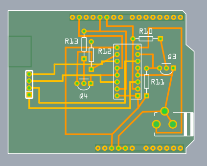
Figure 2. Wires on top and bottom layers.
Normally, both top and bottom layers are active, so if you draw a trace between connectors, you will most likely draw it on the top layer (since the bottom layer lies beneath the top layer). There are two ways you can directly choose which layer you’re working on. The first method you may already be familiar with: under the View menu, hide the layer you don’t want to work with. The same functionality is also available from the Layers palette (available under the Window menu), and if you’re doing a lot of switching back and forth, you may find the Layers palette more convenient.
The second method is new with this release of Fritzing: instead of completely hiding a given view, this method dims one of the layers and makes it ignore mouse clicks.
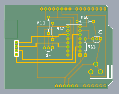
Figure 3. Top layer active, bottom layer inactive.
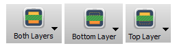
There are two ways to access this functionality: on the Trace menu, there are three items, “Set both copper layers clickable”, “Set copper bottom layer clickable”, and “Set copper top layer clickable”. There is also a new button next to the autoroute button for toggling between these three choices.
And speaking of the autoroute button, the autorouter has been updated to work with both sides.
- First, as before, it will try to route everything on the bottom layer, and it will mark each failed connection with a blue jumper wire.
- Second, the autorouter will attempt to route those unrouted connections on the top side.
- Third, if there are still any unrouted connections, the autorouter will try to place a jumper item (part).
- If even that fails, the jumper wire remains.
Although this version of Fritzing supports vias3 for manual routing, vias are not yet used in the autorouter. In an upcoming Fritzing release, before trying a jumper item, the autorouter will try to route using a via.
That’s it. Happy routing.
1. For home-brew experts, SMD parts can be added to the bottom layer on single-sided boards.
2. Changing board layers will affect SMD parts, which will be disconnected, flipped, and added back to the other side.
3. A “via” is a plated through-hole. It’s a way of routing a connection from one side of the board to the other. In Fritzing, you can drag a via into your sketch from the Parts Bin.
Fritzing is not tied to the use of an Arduino, in fact you don’t need to use a microcontroller at all. We are very aware that many communities exist around a wealth of other nice microcontroller boards, and we would like to support them as well!
So with some support from the producers of the board themselves, we are introducing further microcontroller alternatives into the Fritzing ecosystem. In the new release, due tomorrow, you will already get this sweet array of choices:
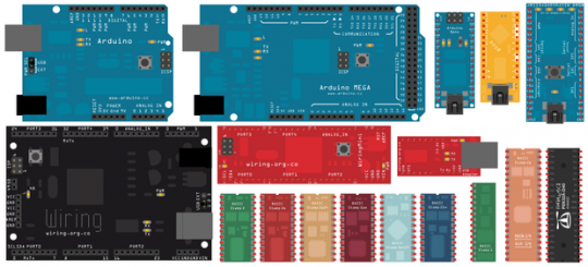
Besides the Arduino and its variants Mega and Nano, you can now use:
- Modified's pico, an Arduino-compatible micro-scale board (thanks to Brian Evans)
- mbed, a new ARM-based microcontroller on steroids (thanks to Simon Ford)
- Wiring and Wiring Mini, Arduino's sister project (thanks to Hernando Barragán)
- Basic Stamp, the classic from Parallax in all its colorful variations (thanks to Ken Gracey)
- Propeller, the new multicore processor from Parallax (also thanks to Ken)
Plus, in the community contributed section you can find: the Mignon Game Kit (thanks to Olaf Val), theBare-Bones Board (thanks to Janis), the Pks-01 (thanks to Michael Franz), and the Ardweeny (thanks to Cameron Behar).
And more are coming up!
What does it mean to you? Well, besides being able to document and share your projects with everyone, this allows you to easily create pcbs for them, either as shields or with a plug for your favorite microcontroller.
Let us know which microcontroller you are still missing, in the comments!
Comments from the old Blog:
- Nathan Andrew Fain #16. April 2010, 02:59fritzing updates, ymmy! teensy and teensy++ would be great: https://www.pjrc.com/teensy/index.html
- André Knörig #16. April 2010, 11:10Yeah, they are nice and not so difficult to make. We'll try to include them soon!
- joshuajnoble #17. April 2010, 16:45Nice work! I definitely think teensy would be nice too.
- dmaugis #27. Mai 2010, 23:50I try to do a part for BV511, an ARM LPC2132 board by ByVac. https://www.byvac.co.uk/mi_bv511.php
- whitedragon #13. Juli 2010, 11:12Nice work just wondering when the ardunio pro mini will be ready
It was so obvious that we were surprised ourselves: not only can you transfer your physical breadboard sketch easily into Fritzing, you can also do it the other way around.
Just load a Fritzing sketch and print it on a sheet of paper, and you have a nanometer-perfect paper template which you just have to fill in with the real parts. Good thing that Dirk was so strict about matching the scale to reality.
Here’s how it goes:
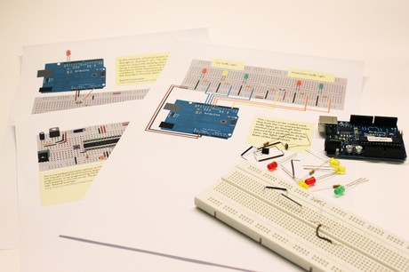
- Cut off a corner of the page so it’s easier to align the printed breadboard with the physical one.
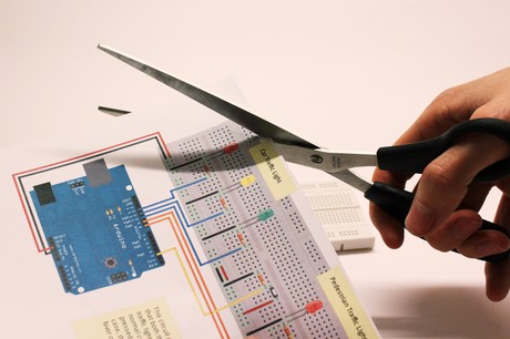
- Stick the parts and wires through the holes. You might want to use a needle to prepare the holes.
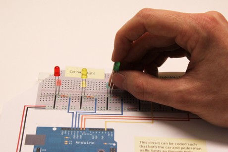
- Connect the Arduino and load the associated code - done!
Now if that’s not a great learning tool..
Small caveat: Depending of your brand of breadboard, its power/ground lines might not line up perfectly. So double-check before trying to punch your parts into the plastic. ;)