Fritzing 1.0.7 brings native Apple Silicon support, a major Qt framework upgrade, improved performance, and a massive expansion of our Adafruit parts library.

What’s New
Native Apple Silicon Support
Mac users with Apple Silicon (M1 - M5) can now run Fritzing natively without Rosetta translation. This brings significantly improved performance and better energy efficiency on modern Macs. Whether you’re working on a MacBook Air or a Mac Studio, you’ll experience faster launches, smoother interactions, and cooler operation.
Qt 6.8.3 Framework Upgrade
We’ve upgraded the underlying Qt framework from 6.5.3 to 6.8.3. This was a significant effort that required fixing copper fill rendering, font rendering issues, and various compatibility adjustments. The upgrade brings better platform integration, improved text rendering, and numerous upstream fixes.
Part icons are now loaded from the database with lazy SVG loading and an in-memory cache. This means faster startup times and smoother scrolling through parts bins, especially noticeable with our growing parts library.
Expanded Adafruit Parts Library
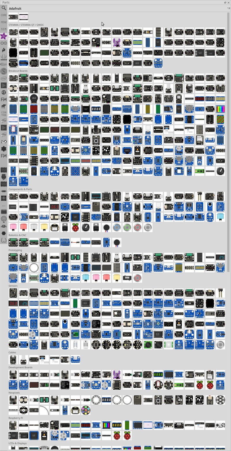
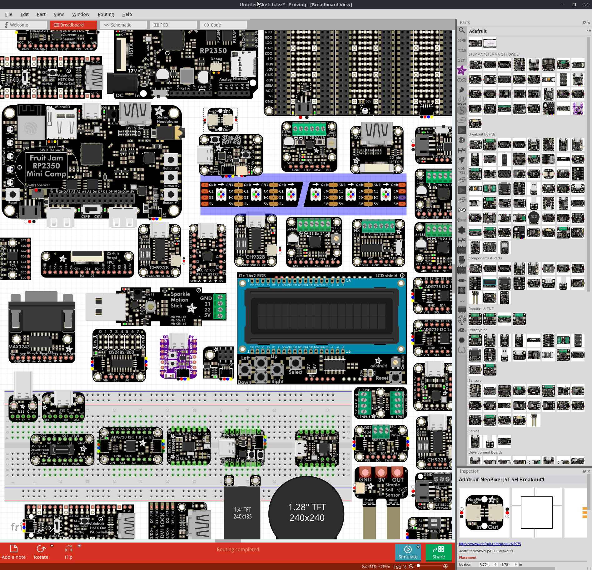
We’ve imported around 300 additional Adafruit parts, further expanding the dedicated Adafruit parts bin introduced in 1.0.6.
These are too many parts to fit into a single screenshot, here it is anyways:
Bug Fixes and Improvements
PCB and Routing
- Fixed copper fill and ground fill not working #4281
- Fixed multiple traces being treated as one when connected in series #4290
- Fixed duplicate aperture in Gerber contour files #4296
Rendering and Fonts
- Fixed font rendering appearing blurred or bold #4282
- Fixed schematic net label width broken with Droid Sans font #4300
- Fixed notes line spacing and font size
- Updated OCR-Fritzing-mono font with ground, celsius, and fahrenheit glyphs
Parts and Editor
- Fixed Parts Editor “Close without saving” and “Keep working” buttons being reversed #4297
- Obsolete parts no longer appear in the inspector swap combobox
- Capacitance values are preserved when migrating obsolete capacitors
- User parts now stored in organized subfolders by module ID #4188
Stability
- Fixed crash on drag and drop with invalid mime data
- Fixed potential data loss when saving sketches on macOS
- Fixed segfault caused by null cursor and empty view checks
- Improved error messages for misbundled sketch files
Other
- Recent file list preserved across version upgrades
- Full paths no longer stored in sketch files, improving portability and privacy
- Added generic small 6V solar panel
- Updated translations for German, French, Spanish, Japanese, Italian, and Portuguese
OS Requirements
- macOS: Big Sur (11) or later, native Apple Silicon and Intel support
- Windows: Windows 10 64-bit or later
- Linux: Ubuntu 22.04 or later (glibc 2.35+)
The release is available in our downloads section. We recommend all users upgrade to benefit from the stability and performance improvements.
The Fritzing 1.0.6 release is focused on stability, performance improvements, and the parts library.
We tested it on Windows 11 25H2, Windows 11 24H2 (ARM and Intel), macOS Tahoe, macOS Sequoia, macOS Ventura, Fedora 42, Debian 13.1.0, Manjaro KDE 25.0.9, Mint 22.2 Mate, Ubuntu 22.04, Ubuntu 24.04, and Ubuntu 25.10.

What’s New
Adafruit Parts Bin
We’re excited to introduce a dedicated Adafruit parts bin featuring 83 carefully curated components from our friends at Adafruit. This collection includes many of the most popular maker-friendly parts that the community loves - from sensors and displays to breakout boards and development modules. Having these parts readily available in Fritzing makes it even easier to prototype your next project with components you can actually buy and build with.
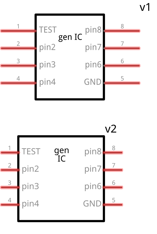
Generic IC Improvements
Did you know Fritzing has generic ICs? Many users overlook this powerful feature that lets you create custom integrated circuits for any chip you need. In this release, we’ve made some incremental improvements to make them even more useful:
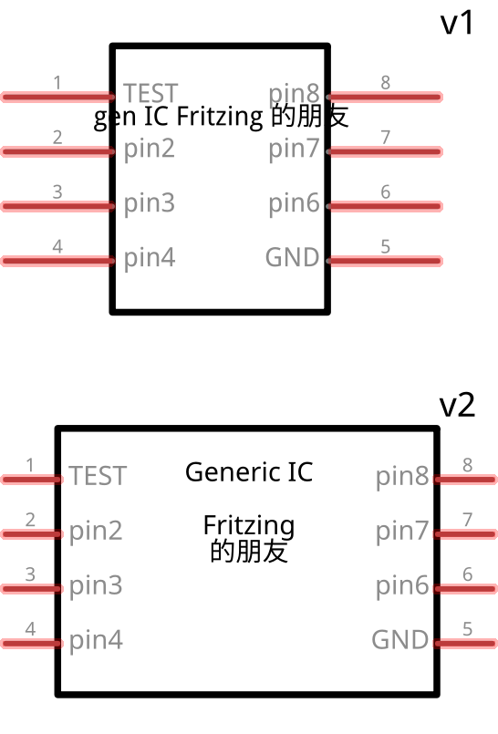
The generic IC now supports multiline labels and uses our improved font system (Noto Sans + OCR-Fritzing-mono) for better readability. We’ve also standardized the pin spacing to 1 unit in schematic view and improved text wrapping that automatically breaks at spaces and newlines while respecting non-breaking spaces.
The component also respects non-breaking whitespaces (U+00A0 and U+202F) for precise text formatting control.
Work in progress: We’re overhauling the package switching system for this component - more improvements coming soon!
We’ve implemented several behind-the-scenes optimizations that make Fritzing noticeably more responsive. Whether you’re working with complex multi-board projects or browsing through large parts databases, you’ll experience smoother interactions and faster load times throughout the application.
Bug Fixes and Improvements
Parts and Components
User Interface
- Fixed straightening lines disabled in schematic view
- Resolved error messages being too large to close
- Improved center-to-screen (Ctrl+0) functionality
- Fixed dark mode font color inconsistencies in upload screen
- Fixed splash screen vanishing when clicked on Windows
- Improved metadata editor with proper labels #3996
- Resolved issues with off-grid component movement on PCB view #4196
- Improved pad selection behavior in PCB view
Ground Fill and Copper Fill
- Fixed ground fill adding shorts across power supplies #4254
- Added warnings when ground fill can’t connect due to no path #4226
- Improved ground fill split detection and warnings
Export and File Handling
- Fixed IPC netlist issues with buses and switches
- Improved Gerber export is now enabled by default
- Fixed PNP export random ordering
Others
- Fixed incorrect version display #4244
- Hide obsolete parts in the search #4151
OS Requirements
- The minimum macOS version is Big Sur
- Windows 10 or 11 are supported on x86 CPUs
- Windows 11 (24H2 and later) is supported on x86 and ARM CPUs
- For Linux, Fritzing requires glibc >= 2.31 and OpenSSL 3 (64-bit Intel/AMD)
- Ubuntu 22.04 or later is recommended, though Fritzing should also run on Ubuntu 20.04
The release is available in our downloads section.
We highly recommend updating to this version to benefit from the latest improvements and bug fixes.
Fritzing 1.0.5 is a maintenance release.
It has been tested on Windows 11 24H2 (ARM and Intel), macOS Sequoia, macOS Ventura, Ubuntu 22.04, and Ubuntu 24.04.

What is new
Windows ARM Support for Windows on ARM CPUs. Fritzing uses Prism on Windows 24H2 to run on ARM.
New Fonts We are fading out Droid Sans and Open Sans in favor of Noto Sans.
This affects mostly the Breadboard and the Schematic View. A bunch of Fritzing parts was using unknown fonts,
which resulted in using whatever fallback font the operating system provided. We have replaced these with either Noto Sans, or OCR-Fritzing-mono.
This results in better i18n support, and fixes several font related bugs.
Sketches will be more consistent when shared between different OSes. We tried to iron out some subtle differences between
OpenType (Linux), Core Text (MacOS) and DirectWrite (Windows) font rendering. Fritzings additional SVG layer made this quite difficult.
Speed We added an option to enable hardware acceleration. Start Fritzing with --opengl to enable it.
The speed gain is notable with some complex sketches, but not huge. In some cases, it will just save battery power,
in others you might see a 20-30% speed improvement.
Bug Fixes
- Fixed crash when loading .fzbz files containing parse errors
- Fixed crash that occurred when swapping packages without any matching connectors
- Corrected bounding box size for text items placed in sketches
- Fixed undefined connectors for the D31A* relay.
- Fixed sparkfun-relay display issue where it appeared as a red rectangle.
- Fixed issue where resistance was displayed twice in component properties.
- Fixed application crash that occurred during export operations.
- Fixed unexpected switching to image logos
- Fixed unexpected bold fonts usage
- Fixed disappearing LogoItems after type switch
- Corrected font size calculation across macOS, Windows, and Ubuntu.
- Fixed rotation and flipping issues in SVG export for IC and Mystery part pin labels.
- Fixed relay parts to properly fit on breadboards and added spice models.
New parts

- Infineon XMC1400 Kit with support for shields and CAN interface
- Infineon PSoC™ 6 Artificial Intelligence Evaluation Kit (CY8CKIT-062S2-AI)
- Infineon Boot Kit XMC1100
- Strawberry Linux SHT-25 High-precision single-chip temperature and humidity sensor module (THT and SMD)
- Dual Color LED 8mm
OS Requirements
- The minimum macOS Version is Big Sur.
- Windows 10* or 11 are supported on x86 CPUs.
- Windows 11 (24H2 and later) is supported on x86 and ARM CPUs.
- For Linux, Fritzing requires glibc >= 2.31 and OpenSSL 3 (64-bit Intel/AMD).
The latter OpenSSL requirements typically mean Ubuntu 22.04 or later,
but Fritzing should also run on Ubuntu 20.04.
*) Very old versions of Windows 10 that have not been updated since 2016 are not supported!
GitHub Issues
In addition, with some overlap, here is a list of issues that have been
resolved for the 1.0.5 release  .
.
The release is available in our downloads section.
Fritzing 1.0.4 is a maintenance release.
It has been tested on Windows 10, Windows 11, macOS Ventura, macOS Monterey, Ubuntu 20.04, Ubuntu 22.04, and Ubuntu 24.04.

What is new
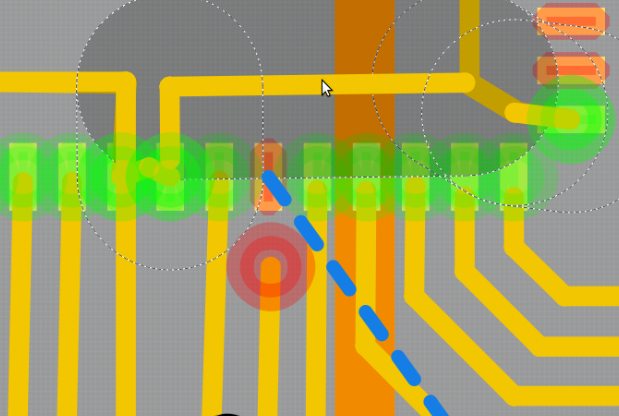
UX: QFN support and working with tiny structures in the PCB was vastly improved. We changed the algorithm that decides which element will receive a mouse click. Ratsnest lines now stay the same size when zooming in. The hitbox size of wires and traces now depends on the wire diameter.
These two images show a PCB at 3000% zoom. The copper traces are 0.2mm (8mil) wide.
Working at this scale was quite annoying in previous versions of Fritzing:
 The second image shows Fritzing 1.0.4. We made UI elements scale to proper sizes.
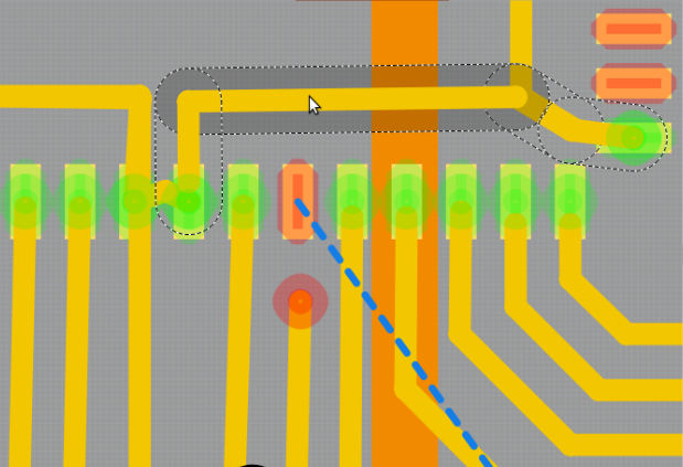 There are quite a number of these changes. More situations where these apply can be seen in issue 3177 on github.
UX: Creating multiple wires of the same size or color is now much easier, as the properties of the recently created wire will also be used for new ones.
Board images: The alpha channel is now taken into account when loading board images. This also fixes many cases where loading an image would result in garbage or blank output.
UX: Show a message when a part must be moved to delete a ratsnest line. Before, we just moved parts without notice.
Bug Fixes
- Fixed crash when using the keyboard for moving parts.
- Fixed ghost connections resulting from moving parts over existing connections.
- Fixed ghost connections when moving a part via the keyboard.
- Fixed error when saving sketch to a write protected destination.
- Fixed repeated read/write operations when saving a sketch, to avoid issues with cloud storage.
- Fixed inactive copper layer after a board was deleted.
- Fixed an error where a move or rotate command was not properly stored, which would result in incorrect undo operations.
- Fixed order of text input fields in Inspector. They were in random order, often changing.
- Fixed input for decimals to work in all locales for text size (Inspector).
New parts
We included the PSoC™ 6 Artificial Intelligence Evaluation Kit (CY8CKIT-062S2-AI), thanks to Janarthanan Nagarajan from Infineon,
and the Calliope Mini 3, thanks to Harald Rau.
OS Requirements
The minimum macOS Version is Big Sur.
Windows 10* or 11 are supported on x86 CPUs.
For Linux, Fritzing requires glibc >= 2.31 and OpenSSL 3 (64-bit Intel/AMD).
The latter OpenSSL requirements typically mean Ubuntu 22.04 or later,
but Fritzing should also run on Ubuntu 20.04.
*) Very old versions of Windows 10 that have not been updated since 2016 are not supported!
GitHub Issues
In addition, with some overlap, here is a list of issues that have been
resolved for the 1.0.4 release
.
The release is available in our downloads section.
Fritzing 1.0.3 is a maintenance release.
It has been tested on Windows 10, Windows 11, macOS Ventura, macOS Monterey, Ubuntu 20.04, Ubuntu 22.04, and Ubuntu 24.04. It is designed to work on all Linux variants with glibc >= 2.31 (64-bit Intel/AMD).

Changes since 1.0.2.
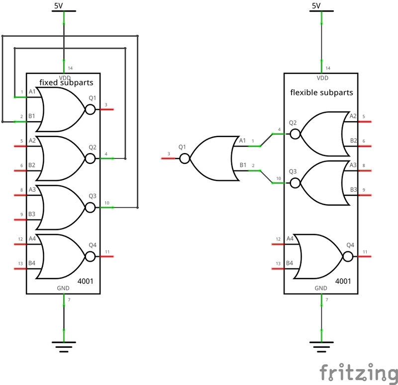
Subparts
A number of issues with schematic multiparts have been fixed.
Basic operations like Undo/Redo on multiparts and their subparts were lacking and are now complete.
Subparts can be used to clean up the schematic view. This example shows a 4001 Logic IC.
The gates can be freely arranged to gain a much cleaner and more readable look:
Dark Mode Bugs
Several bugs where Fritzing was not readable in Dark Mode have been fixed.
OS Requirements
The minimum macOS Version is Big Sur.
Windows 10* or 11 are supported on x86 CPUs.
For Linux, we need glibc >= 2.31 and OpenSSL 3. The latter OpenSSL requirements typically mean Ubuntu 22.04 or later,
but Fritzing should also run on Ubuntu 20.04.
*) Very old versions of Windows 10 that have not been updated since 2016 are not supported!
Outlook
If you have a close look, you will see that we started work on a transitory simulator. This feature is not
yet finished. You can try it by starting Fritzing in debug mode (-d option). It may not work at all, or even
crash, though. There is still a lot missing.
GitHub Issues
In addition, with some overlap, here is a list of issues that have been
resolved for the 1.0.3 release
.
The release is available in our downloads section.