
After many requests and years of waiting, Fritzing finally got a simulator!
The primary purpose of the simulator is to teach electronics to beginners, and its current capabilities are very limited (only analysis of DC circuits). However, it is fully functional, easy to use, and works on the breadboard and schematic view. In addition, it performs some checks to see if any parts are working outside their specifications.
In this blog post, we will teach how to use the simulator step by step.
Installation and enabling the simulator
The simulator is only available in Fritzing 0.9.10 or later versions. It is disabled by default. To enable it, go to Edit->Preferences (or ⌘+, File->Preferences in macOS), select the “Beta Features” tab, and check the “enable simulator” checkbox. Fritzing will save this option, and you will only need to activate the simulator once. Of course, you can still disable it anytime in the preferences dialog.
After the simulator is enabled, you will see a simulate button next to the share button at the bottom bar.
Running examples
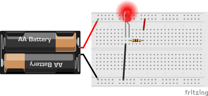
Let’s start by opening the LED example. Go to File->Open Example->Simulator->Basic Circuits->LED.
This is a very simple circuit with an LED, a resistor, and a battery. Once the example is loaded, press the simulate button. The LED switches off as the resistance is too high, and very little current flows through the LED. Try to reduce the value of the resistor. For example, set the resistance to 30Ω. To do that, select the resistor and change the resistance property in the Inspector pane. As soon as the resistance is changed, the simulator will simulate the circuit again, and you will be able to see the light coming out of the LED. Now try changing the 3V battery to a 9V one (in the Inspector pane). The simulator recalculates the current that flows, and now this current is too high, so it breaks the LED and the resistor. This is indicated by a smoke symbol on top of the LED and the resistor. You can fix it by setting a higher resistance or changing the resistor’s power and the LED’s maximum current.
Measuring voltages and currents
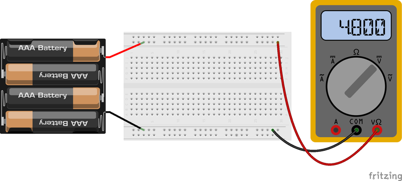
The simulator tries to recreate what you would experience when working with real hardware. Thus, you can use a multimeter to measure voltages, currents, and resistances. The best way of experiencing this is to start with the examples contained in File->Open Example->Simulator->Multimeter.
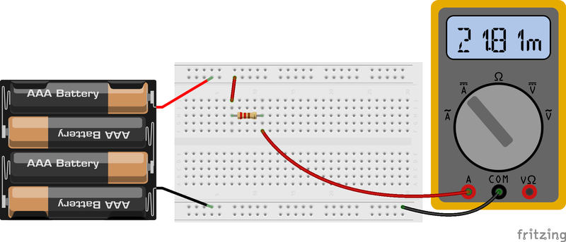
Let’s open the example called “How to measure DC voltages”. In this example, a multimeter is connected to measure the voltage of a battery. When you press the simulate button, the multimeter will show the battery’s voltage. Change the battery voltage, and you will observe how the multimeter’s display updates the voltage. Now, open the “How to measure DC currents” example. Change the value of the resistor to change the current that flows through the multimeter. Notice that the multimeter displays the numbers in engineering notation (e.g., 17.5 mA means 0.0175 A).
Breadboard view or schematics view
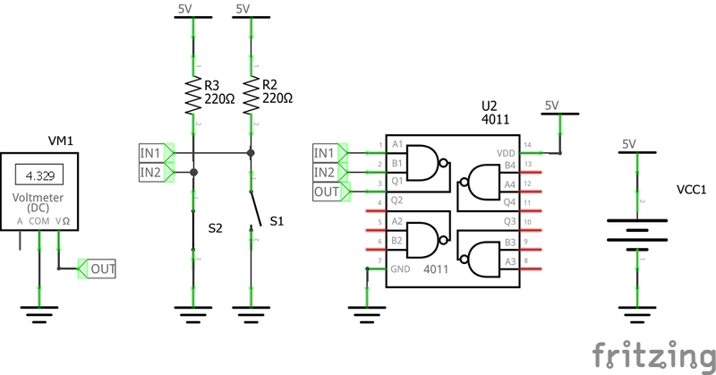
While the previous examples are shown in the breadboard view, the simulator can work in any view. You only need to wire one view, but of course, you can also wire all of them. For example, below, you can find a NAND gate being simulated in the schematics view and where the input signals are controlled with switches.
Error checking
As we have seen in the LED example, the simulator checks that the simulated devices are within their specifications. A smoke symbol is added on top of a device if it’s working outside its specifications.
Currently, we have implemented these tests:
- Three probes connected to a multimeter or wrong probes connected (Err message on the screen appears)
- Short circuit in batteries
- Max current (diodes and LEDs, TODO: inductors)
- Max power (resistors)
- Reverse voltage (tantalum and electrolytic capacitors, IR sensors)
- Max voltage (capacitors, motor, IR sensors)
Using the simulator from scratch
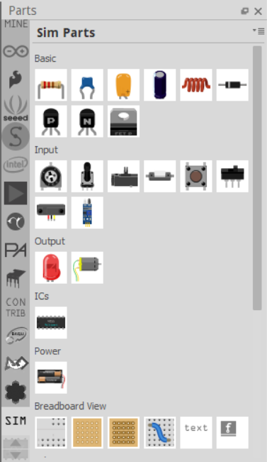
You are encouraged to simulate your own circuits, but be aware that currently, only a few Fritzing parts contain simulation models. Thus, several parts cannot be simulated. The best solution to avoid problems is to use the “Sim Parts” (SIM) bin. In the bin selector, scroll down with the arrows until you find the SIM bin. All the parts included in this bin can be simulated.
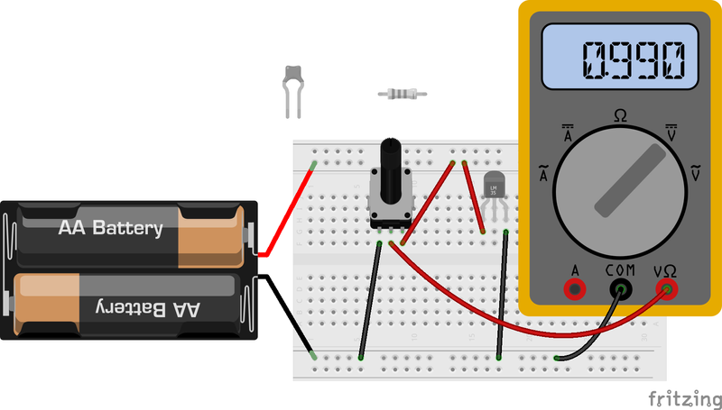
If a circuit contains parts that do not have a simulation model, they will automatically be ignored in the simulation. In addition, they will be greyed out to indicate that they are not taken into account in the simulation. Notice that parts can also be grayed out even if they have a simulation model. This happens if the part is not connected to the rest of the circuit. In the example below, the resistor and the capacitor are not part of the circuit, and the temperature sensor does not have a simulation (SPICE) model.
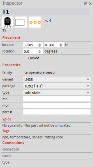
The simulation model of a part is shown in the Inspector pane. So, if you are in doubt, check the SPICE field in the Inspector pane. If it cannot be simulated, it will be clearly indicated there. We can observe that if we select the temperature sensor in the previous example, as shown in the next figure.
Currently, only a few types of devices are supported:
- Resistors
- Capacitors
- Inductors
- Switches
- Potentiometers
- Diodes
- LEDs
- Transistors (Bipolar Junction and FET)
- Multimeters
- IR sensors
- DC motor
- Batteries
- NAND gates
The status of the switches and potentiometers can be changed through a menu in the inspector pane. The switches change their images based on their status (pressed/released) in the breadboard view and the schematics view. Currently, the position of the knob in the potentiometers is not updated. The only output devices which the simulator handles are the LED and DC motors. LEDs change their color based on the current that flows through them. RGB LEDs are currently not supported. DC motors show an arrow if they are rotating (indicating their direction of rotation).
Notice that currently, the simulator can only simulate one circuit per file. If you have several independent circuits, you can merge them by connecting their grounds together.
Power symbols in the schematic view do not provide voltage. Add a DC power supply and connect it to a ground symbol and a power symbol.
Finally, you can stop the simulator by pressing the stop button. This is very handy when you are wiring your circuit. Of course, you can activate it later by pressing the simulate button.
Citing the simulator and academic paper
If you are interested in more specific details of the simulator and its use for teaching electronics online, please take a look at the paper: Andres Faiña, “Learning Hands-On Electronics from Home: A Simulator for Fritzing”, Accepted in the proceedings of the 25th International Conference Series on Climbing and Walking Robots (CLAWAR 2022). Available at https://arxiv.org/abs/2206.07146.
Warning
The simulator is still in beta status and could have bugs that let Fritzing crash. Please help us improve it by reporting them at the issue tracker. And of course, if you think you can help us with the development, you can contact us or send us a pull request. There are several parts that need SPICE models!
Andres Faiña and the Fritzing Team.