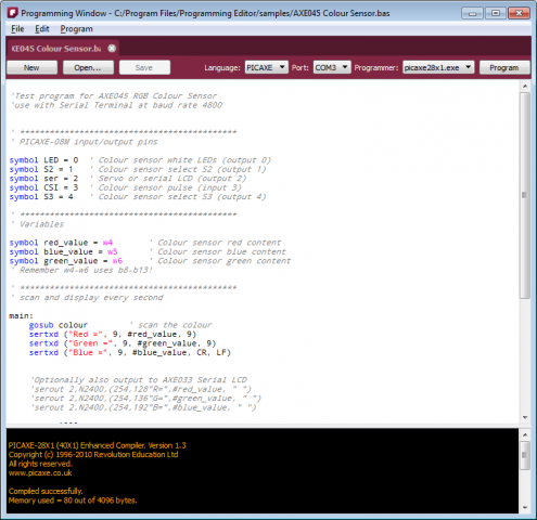
The latest release of Fritzing (0.4.0) has a surprise new experimental feature: a programming window. It’s intended to be a place to type your script for downloading to a microcontroller, and then actually download it. It’s not intended to replace your usual microcontroller programming environment. Rather, it’s meant to be a lightweight alternative, particularly useful for novices, workshops, and classrooms. It’s also a nice way to keep both your sketch and script files together.
At the moment, Fritzing only fully supports the PICAXE microcontroller, and only on the Windows platform. While there is support for typing in Ardiuno programs, we do not yet handle the download part (and that may have to wait for the release of Arduino 1.0).1
There is one programming window per sketch, but a programming window can have multiple tabs. The reason for multiple tabs is that we imagine you might want to play with slightly different versions of the same script until you hone in on one.
Aside from the standard file and edit commands, there are four steps you need to perform.
- First, choose the microcontroller language for your script. Right now there are two choices, Arduino and PICAXE.2 Once you choose a language, you will notice that the script you're working on is highlighted according to that language, and also that you can only save or load files with the appropriate extension.
- Second, select a serial port. First plug in your microcontroller into your USB port. This should create a new USB serial port for that device, which should now be listed when you click on the port combo box.
- Third, select a programmer (i.e. the executable which will compile and download your script). Fritzing does not install these programs for you, you have to do it yourself.
- Fourth, hit the program button. Feedback from the programmer should be displayed in the console area on the bottom of the programming window.
Here’s an image. As usual, we will be refining the implementation and UI in future releases.
A couple of acknowledgements. This work was partly sponsored by PICAXE (grateful thanks to Clive). And thanks to Bryant–our first new major code contributor–for co-implementing this feature.
That’s it, happy programming.
1. For the technically minded, here is the explanation: right now there’s not a simple way to invoke the Arduino compiler and downloader via shell command(s). This feature is slated for Arduino 1.0.
2. There are two requirements for adding a new language to the programming window. First, to enable syntax highlighting, Fritzing implements a subset of Kate Highlighting XML. So a new Kate Highlighting XML file has to be provided for each new microcontroller language. You can find the current set of highlighting files in your Fritzing installation folder, in the …/translations/syntax folder. The second requirement is to find a compiler/downloader for the microcontroller that can be accessed via shell commands.
One of the biggest and earliest requests for Fritzing was for it to handle double-sided (i.e. two-layer) boards. For those who don’t know, a two-layer board means you can route traces between connections on both the front and the back sides of the board, so compared to single-layer boards, this can save hand-wiring after etching, and the board will be more reliable.
We are pleased to announce that double-sided boards are supported in latest release of Fritzing (0.4.0). We tried to build in the minimal necessary functionality, and we’d like to hear your feedback about what’s still missing (and what’s buggy–we made a lot of changes from 0.3.19). For example, though Fritzing 0.4.0 supports wiring on both sides, it only supports adding parts to the top1 (which is what you do currently). If there’s a big demand for adding parts to the bottom, we will include this in a later release.
From a UI point-of-view, Fritzing is much the same. In fact, to work with single-sided boards, there is no change at all: just run Fritzing as usual. Your old sketches and parts will be fine. To switch into two-sided mode, go into PCB View, select your board, and in the Inspector palette, select “double-sided” in the combo box labeled “layers”. If you’re already working on a project and want to switch it to double-sided, don’t worry: changing the number of layers from 1 to 2 will not affect any connections2.
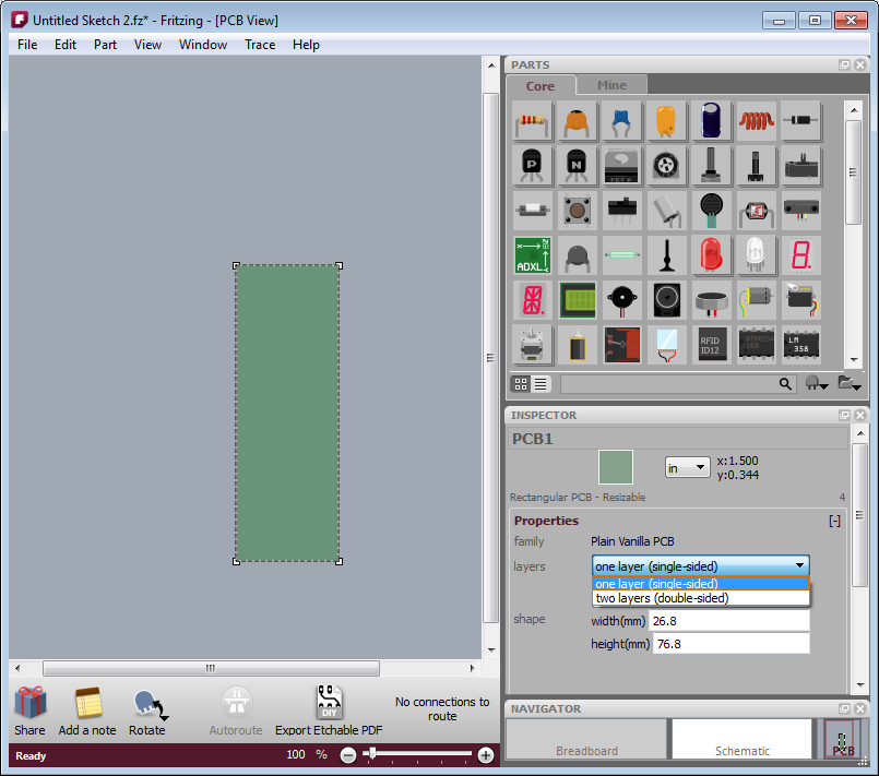
- Figure 1. Using the inspector to change the number of board layers
The way Fritzing models it, in PCB View you’re looking down at the top of the board. Through-hole parts (i.e. most of the parts that are currently in the parts bin), are shoved down through the board, and normally they’re soldered and wired on the other side: on the bottom layer. But now it’s also possible to wire them from the top. Therefore, connectors and traces now exist on both sides of the board. You will notice that traces and connectors drawn on the bottom are slightly darker than traces and connectors drawn on the top.
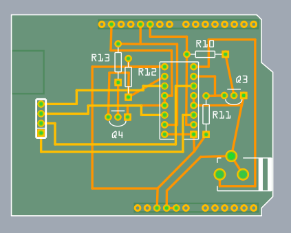
Figure 2. Wires on top and bottom layers.
Normally, both top and bottom layers are active, so if you draw a trace between connectors, you will most likely draw it on the top layer (since the bottom layer lies beneath the top layer). There are two ways you can directly choose which layer you’re working on. The first method you may already be familiar with: under the View menu, hide the layer you don’t want to work with. The same functionality is also available from the Layers palette (available under the Window menu), and if you’re doing a lot of switching back and forth, you may find the Layers palette more convenient.
The second method is new with this release of Fritzing: instead of completely hiding a given view, this method dims one of the layers and makes it ignore mouse clicks.
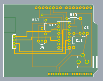
Figure 3. Top layer active, bottom layer inactive.
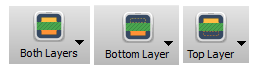
There are two ways to access this functionality: on the Trace menu, there are three items, “Set both copper layers clickable”, “Set copper bottom layer clickable”, and “Set copper top layer clickable”. There is also a new button next to the autoroute button for toggling between these three choices.
And speaking of the autoroute button, the autorouter has been updated to work with both sides.
- First, as before, it will try to route everything on the bottom layer, and it will mark each failed connection with a blue jumper wire.
- Second, the autorouter will attempt to route those unrouted connections on the top side.
- Third, if there are still any unrouted connections, the autorouter will try to place a jumper item (part).
- If even that fails, the jumper wire remains.
Although this version of Fritzing supports vias3 for manual routing, vias are not yet used in the autorouter. In an upcoming Fritzing release, before trying a jumper item, the autorouter will try to route using a via.
That’s it. Happy routing.
1. For home-brew experts, SMD parts can be added to the bottom layer on single-sided boards.
2. Changing board layers will affect SMD parts, which will be disconnected, flipped, and added back to the other side.
3. A “via” is a plated through-hole. It’s a way of routing a connection from one side of the board to the other. In Fritzing, you can drag a via into your sketch from the Parts Bin.