Fritzing 1.0.2 is a feature release. It has been tested on Windows 10, Windows 11, macOS Ventura, macOS Monterey, Ubuntu 20.04, and Ubuntu 22.04. It is designed to work on all Linux variants with glibc >= 2.31 (64 bit Intel/AMD).
Changes since 1.0.1.
Copper fill
The Copper Fill algorithm is now vector based. This fixes a number of bugs along, especially with Ground Fills, most prominent the annoying horizontal gaps in the copper fill. It results in higher precision, and more predictable behavior. It also enables a number of Gerber improvements and new features for PCBs in the future. The old rasterized copper fill algorithm was kept available, so you may compare the two against each other.
Fab upload
Refactored fab upload. We can now send properties like width and height along with Gerber, IPC and BOM. At the same time this will shorten the development cycle when adding new features or fixing bugs.
Data structure fixes
We’ve upgraded Fritzing’s data management, fixing several issues that led to discrepancies between views, missed errors in Design Rule Checks, and invisible, uneditable ‘ghost’ connections in the netlist. To rectify these in existing sketches, a simple delete-and-undo action on the problematic elements will clear the bugs. These improvements, which affect numerous example projects, should result in more reliable and understandable behavior from Fritzing going forward.
Testing infrastructure
We’ve significantly enhanced automated testing, allowing us to conduct hundreds of Fritzing sessions every minute.
Moved to Qt 6.5.3.
Just the due maintenance.
OS Requirements
Minimum macOS Version is now Big Sur, before it was Catalina. Windows and Linux requirements didn’t change, but Linux now must use OpenSSL 3, support for OpenSSL 1.2 was dropped)
GitHub Issues
In addition, with some overlap, the following issues on github were solved:
#4091 A sch wire does not snap to grid for existing wires
#4071 Breadboard view misaligned when directly opening a fzpz
#4077 Parts Editor crashes clicking on empty schematics
#4079 Undo often doesn’t work for Bézier curvatures
#4035 Voltmeter is reading incorrect value when probe is disconnected
#4046 Text lost on Redo
#4093 Hover text for parts and connectors not readable in dark mode with Qt 6.5.3
Fritzing 1.0.1 was released on Wednesday, 06th of September 2023.
We tested it for Windows 11, Windows 10, macOS Ventura, macOS Monterey, macOS BigSur, Ubuntu 20.04, and Ubuntu 22.04.
Summary
This is a maintenance release, with some fixes.
The most obvious fix is for the broken mouse pointer when non integer zoom settings are used. This
affected Fritzing on Windows Notebooks with custom zoom settings.
Also, with this version, the new IPC export should actually become usable.
New part
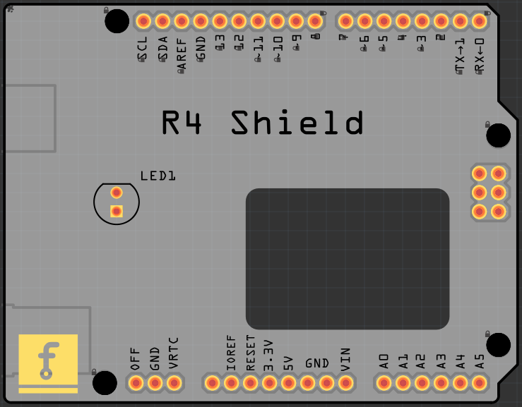
Only a few parts were updated. We added an Arduino sized board with a cutout for the
display. The R4 WIFI has quite a lot of features already onboard. But for sure you have something to add?
Here is a shield for it:
Fixes and Improvements
Fixed issues:
#4023 Redundant entry in fz file
#4036 Trace width lost on Undo
#4037 Mouse cursor distorted on Windows
#4041 Workaround for pixel errors during Gerber export
#4050 IPC Export not working
#4051 Entering coordinates in Inspector not working
#4058 Wire connections not working after double click
Improvements to the SVG Flattener:
Support scaling the stroke-dasharray attribute
Support for inherited fill attributes
Improved viewBox calculation with non-zero x and y values.
UI:
Repaired ‘Paste in place’ command
Keep focus on part after package change
Improved Spanish
Completed Portuguese, thanks to Bruno
Improved Italian, thanks to Sophie
Updated Japanese translation with automatic translation
The release is available in our downloads section.
We highly recommend updating to this version to benefit from the latest improvements.
We are thrilled to announce the release of Fritzing version 1.0.0. This is a major release, with many new features and improvements.
Announcing Fritzing 1.0.0 - A Major Release
Fritzing 1.0.0 was released on Friday, 16th of June 2023.
This major release has been thoroughly tested on Windows 10, Windows 11, macOS Ventura, macOS Monterey, Ubuntu 20.04, and Ubuntu 22.04.
It will work on other Linux variants with glibc >= 2.31 (64 bit Intel/AMD), too.
What’s New in Fritzing 1.0.0
Simulator
The simulator is now officially supported.
We added SPICE data for more parts, like RGB-LEDs and photo cells.
New Font OCR-Fritzing
This font replaces the use of OCR-A. It adds Greek letters, diacritics, and other symbols, like á ä å à é ë è ç ṡ, €, Ω, µ, and ß. This way, it supports almost all European alphabets. Support for Cyrillic is planned.
New IPC-D-356 Export
Export to IPC-D-356 has been added. This enables third parties to verify the PCB correctness during production and render 3D views of Fritzing projects.
Pick and Place
We have reworked the pick and place file export. We now use the suffix ‘.xy’ for pick and place files. A ‘mount’ column was added to distinguish between through-hole and surface mount technology. The new format is ‘RefDes, Value, Package, X, Y, Rotation, Side, Mount’. The gerbv tool understands this and can render pick and place information, along with drill holes and other PCB layers.
Gerber Export
We have improved Fritzings Gerber export feature, which is crucial for turning your digital designs into physical circuit boards.
The ability to determine which areas should be covered with copper (represented by color in the design) has been improved.
Dashed rectangles in the silkscreen should now work as expected.
Very tiny or non-existent drill holes, which could cause issues during the manufacturing process, are now ignored.
Fritzing has also become smarter in maintaining the intended shapes in your design, preventing them from changing due to minor calculation errors.
Additionally, the application can now better handle the thickness of lines in your design.
Lastly, an issue causing distortion in some designs has been fixed, ensuring your final product matches your original design more accurately.
In essence, these updates make Fritzing more reliable and accurate when preparing your designs for manufacturing.
UI Improvements
Several fixes have been implemented to ensure compatibility with dark mode.
These fixes affect the Multimeter, DRC List, Inspector properties, and Search line.
The Inspector has been rearranged to support scrolling and now features flexible previews.
This means, icons and previews can be rendered bigger, which is important on high resolution displays.
The application now supports pinch gestures.
The balance between scroll wheel and gesture zoom has been improved, and the shift key can now be used for fine control.
These enhancements aim to provide a more user-friendly and efficient experience for all Fritzing users.
Maintenance
Upgraded to Boost 1.81
Upgraded to ngspice-40
Upgraded to Qt 6.4.3
Upgraded to C++17
Translations
French, German, Ukrainian, and Russian are now 100% translated again. Nearly complete translations include Bulgarian, Japanese, Portuguese, Vietnamese, Turkish, and Romanian. Many improvements have been made to Spanish.
Fixes and Optimizations
Numerous fixes and optimizations have been made, including rendering slowdown from zooming out, perfboard resize speed up, and many more.
In addition, with some overlap, numerous issues on GitHub were solved.
For more details, please visit the official release page.
Known Issues
The simulator does not work on Catalina and Big Sur. A workaround is planned.
Fritzing 1.0.0 does not support 32 bit systems right now. We might add it again if there is still demand.
Download
The release is available in our downloads section.
We’d love to hear what you think! Write us via our contact form or check out our forum.
Thank you for being part of the Fritzing user group!
After many requests and years of waiting, Fritzing finally got a simulator!
The primary purpose of the simulator is to teach electronics to beginners, and its current capabilities are very limited (only analysis of DC circuits). However, it is fully functional, easy to use, and works on the breadboard and schematic view. In addition, it performs some checks to see if any parts are working outside their specifications.
In this blog post, we will teach how to use the simulator step by step.
Installation and enabling the simulator
The simulator is only available in Fritzing 0.9.10 or later versions.
It is disabled by default.
To enable it, go to Edit->Preferences (or ⌘+, File->Preferences in macOS), select the “Beta Features” tab, and check the “enable simulator” checkbox.
Fritzing will save this option, and you will only need to activate the simulator once.
Of course, you can still disable it anytime in the preferences dialog.
After the simulator is enabled, you will see a simulate button next to the share button at the bottom bar.
Running examples
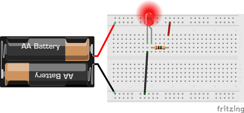
Let’s start by opening the LED example. Go to File->Open Example->Simulator->Basic Circuits->LED.
This is a very simple circuit with an LED, a resistor, and a battery. Once the example is loaded, press the simulate button. The LED switches off as the resistance is too high, and very little current flows through the LED. Try to reduce the value of the resistor. For example, set the resistance to 30Ω. To do that, select the resistor and change the resistance property in the Inspector pane. As soon as the resistance is changed, the simulator will simulate the circuit again, and you will be able to see the light coming out of the LED. Now try changing the 3V battery to a 9V one (in the Inspector pane). The simulator recalculates the current that flows, and now this current is too high, so it breaks the LED and the resistor. This is indicated by a smoke symbol on top of the LED and the resistor. You can fix it by setting a higher resistance or changing the resistor’s power and the LED’s maximum current.
Measuring voltages and currents
The simulator tries to recreate what you would experience when working with real hardware.
Thus, you can use a multimeter to measure voltages, currents, and resistances.
The best way of experiencing this is to start with the examples contained in File->Open Example->Simulator->Multimeter.
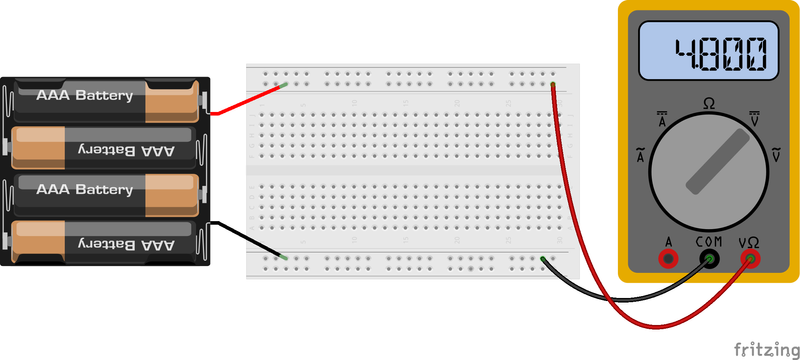
Let’s open the example called “How to measure DC voltages”.
In this example, a multimeter is connected to measure the voltage of a battery.
When you press the simulate button, the multimeter will show the battery’s voltage.
Change the battery voltage, and you will observe how the multimeter’s display updates the voltage.
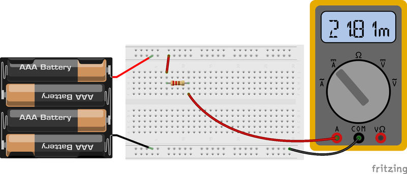
Now, open the “How to measure DC currents” example.
Change the value of the resistor to change the current that flows through the multimeter.
Notice that the multimeter displays the numbers in engineering notation (e.g., 17.5 mA means 0.0175 A).
Breadboard view or schematics view
While the previous examples are shown in the breadboard view, the simulator can work in any view.
You only need to wire one view, but of course, you can also wire all of them.
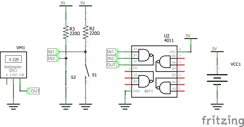
For example, below, you can find a NAND gate being simulated in the schematics view and where the input signals are controlled with switches.
Error checking
As we have seen in the LED example, the simulator checks that the simulated devices are within their specifications.
A smoke symbol is added on top of a device if it’s working outside its specifications.
Currently, we have implemented these tests:
Three probes connected to a multimeter or wrong probes connected (Err message on the screen appears)
Short circuit in batteries
Max current (diodes and LEDs, TODO: inductors)
Max power (resistors)
Reverse voltage (tantalum and electrolytic capacitors, IR sensors)
Max voltage (capacitors, motor, IR sensors)
Using the simulator from scratch
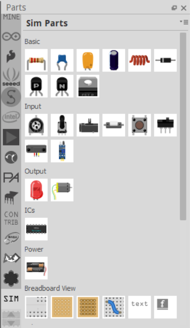
You are encouraged to simulate your own circuits, but be aware that currently, only a few Fritzing parts contain simulation models. Thus, several parts cannot be simulated. The best solution to avoid problems is to use the “Sim Parts” (SIM) bin. In the bin selector, scroll down with the arrows until you find the SIM bin. All the parts included in this bin can be simulated.
If a circuit contains parts that do not have a simulation model, they will automatically be ignored in the simulation. In addition, they will be greyed out to indicate that they are not taken into account in the simulation. Notice that parts can also be grayed out even if they have a simulation model.
This happens if the part is not connected to the rest of the circuit.
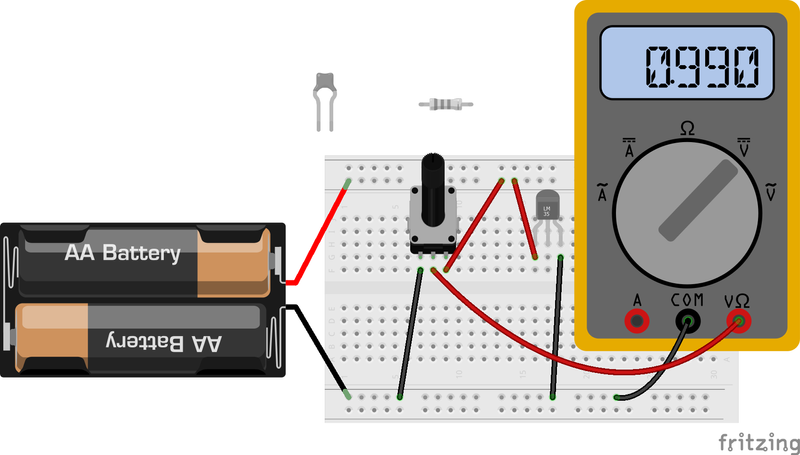
In the example below, the resistor and the capacitor are not part of the circuit, and the temperature sensor does not have a simulation (SPICE) model.
Fig.4 unspiced parts greyed out
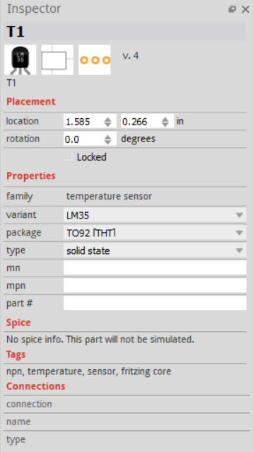
The simulation model of a part is shown in the Inspector pane.
So, if you are in doubt, check the SPICE field in the Inspector pane.
If it cannot be simulated, it will be clearly indicated there.
We can observe that if we select the temperature sensor in the previous example, as shown in the next figure.
Currently, only a few types of devices are supported:
Resistors
Capacitors
Inductors
Switches
Potentiometers
Diodes
LEDs
Transistors (Bipolar Junction and FET)
Multimeters
IR sensors
DC motor
Batteries
NAND gates
The status of the switches and potentiometers can be changed through a menu in the inspector pane. The switches change their images based on their status (pressed/released) in the breadboard view and the schematics view. Currently, the position of the knob in the potentiometers is not updated. The only output devices which the simulator handles are the LED and DC motors. LEDs change their color based on the current that flows through them. RGB LEDs are currently not supported. DC motors show an arrow if they are rotating (indicating their direction of rotation).
Notice that currently, the simulator can only simulate one circuit per file. If you have several independent circuits, you can merge them by connecting their grounds together.
Power symbols in the schematic view do not provide voltage. Add a DC power supply and connect it to a ground symbol and a power symbol.
Finally, you can stop the simulator by pressing the stop button. This is very handy when you are wiring your circuit. Of course, you can activate it later by pressing the simulate button.
Citing the simulator and academic paper
If you are interested in more specific details of the simulator and its use for teaching electronics online, please take a look at the paper:
Andres Faiña, “Learning Hands-On Electronics from Home: A Simulator for Fritzing”, Accepted in the proceedings of the 25th International Conference Series on Climbing and Walking Robots (CLAWAR 2022). Available at https://arxiv.org/abs/2206.07146.
Warning
The simulator is still in beta status and could have bugs that let Fritzing crash. Please help us improve it by reporting them at the issue tracker. And of course, if you think you can help us with the development, you can contact us or send us a pull request. There are several parts that need SPICE models!
Fritzing 0.9.10 was released on Sunday, 22nd of May 2022.
We tested it for Windows 10, Windows 11, macOS Monterey, macOS BigSur, macOS High Sierra, Ubuntu 18.04, Ubuntu 20.04, and Ubuntu 22.04.
Simulation is one of the most requested features of Fritzing.
For more than a decade, people have asked for Fritzing to simulate circuits.
There can be very different expectations about the scope of the simulation.
The simulator is limited to the parts available in the simulation bin.
If a part can not be simulated, it will be greyed out during the simulation.
The simulation was tested by several groups of students, and is now available
as a beta feature.
If you want to give it a try, you can enable it in Fritzings preferences.
Fixes
Fixed issues:
#3943
#3931
#3895
#3880
#3868 , #3820
#3863
#3850
#3830
#3825
#3738, #3602, #1869
#3715, #684
#3632, #3627, #3109
#3559
#2669, #1326
#2583, #2675
Parts
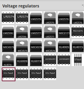
Several voltage regulators added
SeeedStudio Grove Beginner Kit
TDK Ultrasonic sensor module
Amica NodeMCU
About 90 parts received minor fixes
The release is available in our downloads section.
We’d love to hear what you think! Write us via our contact form or check out our forum.