
Nach der Veröffentlichung des Arduino Video Workshops auf Englisch kommt nun die deutschsprachige Synchronisation:
14 Folgen Einsteigerworkshop zum Thema Arduino und Elektronik.
Bitte weitersagen:
Arduino Lernen Episode 001 - Elektronische Grundlagen
Diese Episode klärt ein paar elektronische Grundlagen wie Strom und Spannung, Leistung und Arten von Stromkreisen.
Arduino Lernen Episode 002 – Arduino Überblick
Diese Episode stellt das Arduino-Board vor.
Arduino Lernen Episode 003 – Digital Out mit Blink
Diese Episode klärt, was ein digitales Signal ist und wie ein Programm auf das Arduino übertragen wird. Dazu gibt es einen Einstieg in die Programmierumgebung von Arduino.
Arduino Lernen Episode 004 – Digital Out mit SOS
Diese Episode erklärt for-Schleifen und Arrays.
Arduino Lernen Episode 005 – Breadboard Prototyping
Breadboards sind sehr praktisch um Ideen schnell umzusetzen. Diese Episode zeigt, wie du damit arbeiten kannst.
Arduino Lernen Episode 006 – Digital In mit einem Taster
Digitaler Input ist das Thema dieser Folge. Erklärt wird auch, wozu ein Dropdown Widerstand gut ist und wie eine if-Abfrage programmiert wird.
Arduino Lernen Episode 007 – Verstärkung mit einem Transistor
Oft benötigen wir Stromverstärkung. Wie das funktionieren kann, erkläre ich hier.
Arduino Lernen Episode 008 – Analog Out mit Fading
Der Unterschied zwischen digitalen und analogen Signalen wird geklärt, PWM vorgestellt und wir senden ein PWM Signal um eine LED zu dimmen.
Arduino Lernen Episode 009 – Analog In mit Servo und Pott
Diese Folge zeigt das Prinzip, analoge Sensoren auszulesen. Wir steuern einen Servo mit einem Potentiometer.
Arduino Lernen Episode 010 – Analog In mit Servo und LDR
Diese Folge zeigt, was ein Referenz-Widerstand ist und wie er benutzt wird, um analoge Sensoren auszulesen.
Arduino Lernen Episode 011 – Serielle Kommunikation
Datenübermittlung vom Arduino zum Computer.
Arduino Lernen Episode 012 – FIRMATA
Diese Episode stellt FIRMATA vor und zeigt, wie Arduino und Porcessing mit einander kommunizieren können.
Arduino Lernen Episode 013 – Platinenlayout mit Fritzing
Diese Episode zeigt, wie du mit Fritzing ein Platinenlayout erstellen kannst.
Arduino Lernen Episode 014 – Module
Diese sehr kurze Folge beschreibt eine gute Möglichkeit, den Funktionsumfang von Arduino zu erweitern.
This years Fritzing gift is something very special: A complete Arduino Workshop!
14 Episodes of compressed knowledge of this famous Microcontroller for free and for you! Please share and comment.
We wish you all a Merry Christmas :)
- Learning Arduino Episode 001 – Electronic Basics
This episode will explain electronic basics like voltage, current, power and different circuits.
- Learning Arduino Episode 002 – Arduino introduction
This episode is introducing the Arduino board.
- Learning Arduino Episode 003 – Digital Out with Blink
This episode will show you, what a digital signal is an how you can transfer a program on the Arduino board. The Arduino programming environment is explained, too.
- Learning Arduino Episode 004 – Digital Out with SOS
This episodes shows the use of for-loops and arrays.
- Learning Arduino Episode 005 – Breadboard Prototyping
Breadboards are very useful to prototype ideas in short time. This episode will show, how to work with it.
- Learning Arduino Episode 006 – Digital In with a button
The digital input is the topic of this episode. The need of a drop down resistor is explained and in programming the if-condition.
- Learning Arduino Episode 007 – Amplification with a transistor
Amplification is needed very often. The main principle of it is shown here.
- Learning Arduino Episode 008 – Analog Out with Fading
The difference between digital and analog signals is explained, PWM introduced and we will send an analog signal out to fade a LED.
- Learning Arduino Episode 009 – Analog In with Servo and Knob
This episode will show the principle of sensing a resistor relation. A potentiometer and even a servo motor will be explained.
- Learning Arduino Episode 010 – Analog In with Servo and LDR
This episode will show you the use of a reference resistor when using analog sensors.
- Learning Arduino Episode 011 – Serial communication
Transmit signals from the Arduino to the computer.
- Learning Arduino Episode 012 – FIRMATA
This episode will show you how to work with Arduino and Processing using the FIRMATA library.
- Learning Arduino Episode 013 – PCB layout with Fritzing
In this episode I will show you, how to make a PCB out of your circuit using Fritzing.
- Learning Arduino Episode 014 – using modules
This episode will show you how to extend your Arduino.
One of the biggest and earliest requests for Fritzing was for it to handle double-sided (i.e. two-layer) boards. For those who don’t know, a two-layer board means you can route traces between connections on both the front and the back sides of the board, so compared to single-layer boards, this can save hand-wiring after etching, and the board will be more reliable.
We are pleased to announce that double-sided boards are supported in latest release of Fritzing (0.4.0). We tried to build in the minimal necessary functionality, and we’d like to hear your feedback about what’s still missing (and what’s buggy–we made a lot of changes from 0.3.19). For example, though Fritzing 0.4.0 supports wiring on both sides, it only supports adding parts to the top1 (which is what you do currently). If there’s a big demand for adding parts to the bottom, we will include this in a later release.
From a UI point-of-view, Fritzing is much the same. In fact, to work with single-sided boards, there is no change at all: just run Fritzing as usual. Your old sketches and parts will be fine. To switch into two-sided mode, go into PCB View, select your board, and in the Inspector palette, select “double-sided” in the combo box labeled “layers”. If you’re already working on a project and want to switch it to double-sided, don’t worry: changing the number of layers from 1 to 2 will not affect any connections2.
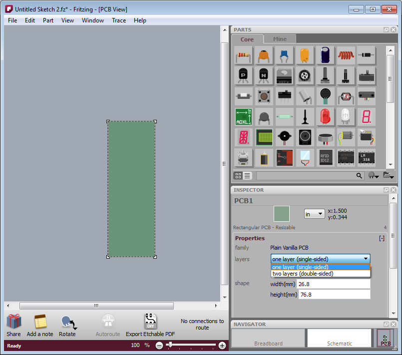
- Figure 1. Using the inspector to change the number of board layers
The way Fritzing models it, in PCB View you’re looking down at the top of the board. Through-hole parts (i.e. most of the parts that are currently in the parts bin), are shoved down through the board, and normally they’re soldered and wired on the other side: on the bottom layer. But now it’s also possible to wire them from the top. Therefore, connectors and traces now exist on both sides of the board. You will notice that traces and connectors drawn on the bottom are slightly darker than traces and connectors drawn on the top.
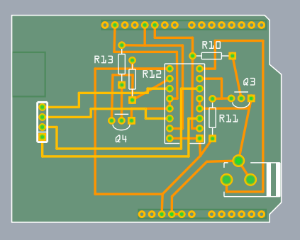
Figure 2. Wires on top and bottom layers.
Normally, both top and bottom layers are active, so if you draw a trace between connectors, you will most likely draw it on the top layer (since the bottom layer lies beneath the top layer). There are two ways you can directly choose which layer you’re working on. The first method you may already be familiar with: under the View menu, hide the layer you don’t want to work with. The same functionality is also available from the Layers palette (available under the Window menu), and if you’re doing a lot of switching back and forth, you may find the Layers palette more convenient.
The second method is new with this release of Fritzing: instead of completely hiding a given view, this method dims one of the layers and makes it ignore mouse clicks.
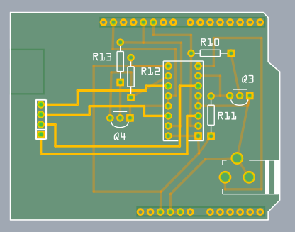
Figure 3. Top layer active, bottom layer inactive.
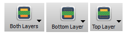
There are two ways to access this functionality: on the Trace menu, there are three items, “Set both copper layers clickable”, “Set copper bottom layer clickable”, and “Set copper top layer clickable”. There is also a new button next to the autoroute button for toggling between these three choices.
And speaking of the autoroute button, the autorouter has been updated to work with both sides.
- First, as before, it will try to route everything on the bottom layer, and it will mark each failed connection with a blue jumper wire.
- Second, the autorouter will attempt to route those unrouted connections on the top side.
- Third, if there are still any unrouted connections, the autorouter will try to place a jumper item (part).
- If even that fails, the jumper wire remains.
Although this version of Fritzing supports vias3 for manual routing, vias are not yet used in the autorouter. In an upcoming Fritzing release, before trying a jumper item, the autorouter will try to route using a via.
That’s it. Happy routing.
1. For home-brew experts, SMD parts can be added to the bottom layer on single-sided boards.
2. Changing board layers will affect SMD parts, which will be disconnected, flipped, and added back to the other side.
3. A “via” is a plated through-hole. It’s a way of routing a connection from one side of the board to the other. In Fritzing, you can drag a via into your sketch from the Parts Bin.