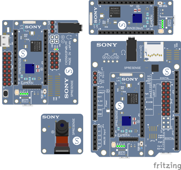
We added Sony’s Spresense modules for Fritzing. Altogether, there are four new parts: the mainboard, the Arduino extension, the LTE extension, and the camera. In this post, we will have a closer look at the Spresense board. We will deploy a Hello World and a Camera example application.
The Spresense parts
The parts are included with recent versions of Fritzing. We highly
recommend using Fritzing with a version >= 0.9.7 .
What are the Spresense modules?
First, there is the main module: Sony’s CXD5602 microcontroller runs a Cortex-M4F CPU with 6 cores, GPS.
The low power consumption makes it suitable for battery-dependent use cases.
There is a great choice of libraries supported, including Python, TensorFlow,
Edge Impulse, Java, JavaScript, and Circuit Python for low power consumption.
Together with GPS, LTE, Wifi, BLE extensions, this makes them suitable for IoT and AI applications.
Then, there is the extension board. It adds Audio input for up to 8 channels, 3.5mm headphone output, an SD-Card slot, an extra USB connector, and the well-known Arduino shield headers.
The third module is the 5MP camera board. With 24mm x 25mm, it is very compact. It connects to the Spresense main module with a flat cable.
And then there is the CXD5602PWBLM1 board, the LTE extension. It adds LTE capabilities to the main module. Also, it has a 3.5mm headphone output, up to four digital microphone inputs, an extra USB connector, and general IO headers.
See the Spresense developer site for more details.
Getting started
For testing, we have set up Ubuntu 21.04 VM and prepared the Software Development Kit with the setup guide from Spresense.
If you are also using a VM, make sure that both, host and guest machine have the “dialout” group
for your user account, so you can access the Spresense board when connected to USB.
The board should be visible as “Silicon Labs CP210x” with lsusb when the board is connected.
If all looks good, we should be able to connect with minicom.
Bus 001 Device 027: ID 10c4:ea60 Silicon Labs CP210x UART Bridge
Bus 001 Device 002: ID 80ee:0021 VirtualBox USB Tablet
Bus 001 Device 001: ID 1d6b:0001 Linux Foundation 1.1 root hub
fritzing@ubuntu: ~ $ minicom -D /dev/ttyUSB0 -b 115200
The connection with minicom will open a NuttShell on our Spresense board. No, this is not yet the ‘Hello World’ we are looking for.
OPTIONS: I18n
Port /dev/ttyUSB0, 23:39:12
Press CTRL-A Z for help on special keys
NuttShell (NSH) NuttX-10.1.0
nsh> echo "Hello World"
Hello World
nsh>
Hello World
Running Hello World on a console is a bit lame. How about using an actual LCD for that? For this, we use an ILI9341 from Adafruit (about $10). We connect it as shown in the Fritzing project below:
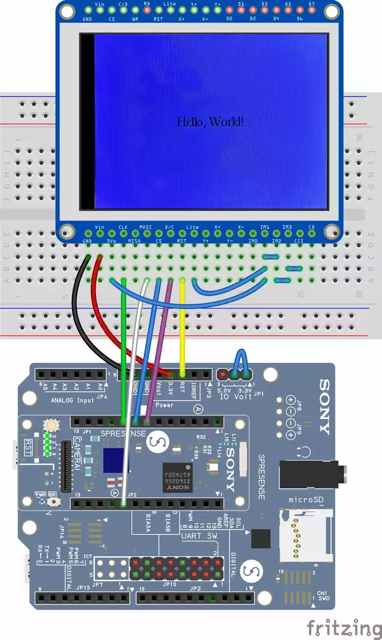
To address the ILI9341 display, the Spresense board needs to know how it is connected. Add the following configuration to the Nuttx kernel, by storing it at ‘spresense/sdk/configs/devices/ili9341_on_spi5/defconfig’
# spresense/sdk/configs/devices/ili9341_on_spi5/defconfig
-NXFONTS_PACKEDMSFIRST=n
+LCD_ILI9340=y
+LCD_ILI9340_IFACE0=y
+LCD_ILI9340_IFACE0_RLANDSCAPE=y
+MMCSD_HAVE_WRITEPROTECT=n
+MQ_MAXMSGSIZE=64
+NX=y
+NXFONTS_DISABLE_16BPP=n
+NXFONT_SERIF22X29=y
+NX_BLOCKING=y
+NX_DISABLE_16BPP=n
+CXD56_DMAC_SPI5_TX=y
+CXD56_DMAC_SPI5_TX_CH=4
+CXD56_DMAC_SPI5_TX_MAXSIZE=1516
+CXD56_DMAC_SPI5_RX=y
+CXD56_DMAC_SPI5_RX_CH=5
+CXD56_DMAC_SPI5_RX_MAXSIZE=1516
+LCD_ON_MAIN_BOARD=y
+LCD_ILI9341=y
+LCD_ILI9341_NINTERFACES=1
+LCD_LCDDRV_SPIIF=y
# The display can run at much higher speeds. But signal quality on the breadboard and the wires can
# vary a lot, so we limit it to 2MHz. Still fast enough for our purpose at 320x200x16
+LCD_LCDDRV_SPEED=2000000
With the config file in place, we can now build the kernel and flash the Spresense board. We
configure it to build the nxhello example and our custom ili9341 setup. Then we run make. If
all was successful, we flash the board. Using the default speed of 115600 did not work reliable,
but with a higher speed of 460800 (or other high values), flashing works quite reliable.
Don’t forget to source ~/spresenseenv/setup, as described in the Spresense getting started documentation.
fritzing@ubuntu: ~ $ tools/config.py examples/nxhello device/lcd_ili9341_on_sp5 && make -j && tools/flash.sh -c /dev/ttyUSB0 -b 460800 nuttx.spk
make[1]: Entering directory '/home/kjell/spresense/nuttx'
make[2]: Entering directory '/home/kjell/spresense/nuttx'
Create .version
make[3]: Entering directory '/home/kjell/spresense/nuttx/boards'
make[3]: Leaving directory '/home/kjell/spresense/nuttx/boards'
make[3]: Entering directory '/home/kjell/spresense/sdk/apps'
make[4]: Entering directory '/home/kjell/spresense/sdk/apps/platform'
make[4]: Leaving directory '/home/kjell/spresense/sdk/apps/platform'
make[4]: Entering directory '/home/kjell/spresense/sdk/apps/builtin'
make[4]: Leaving directory '/home/kjell/spresense/sdk/apps/builtin'
make[3]: Leaving directory '/home/kjell/spresense/sdk/apps'
make[3]: Entering directory '/home/kjell/spresense/nuttx/graphics'
.
.
.
>>> Install files ...
install -b 460800
Install nuttx.spk
|0%-----------------------------50%------------------------------100%|
######################################################################
196432 bytes loaded.
Package validation is OK.
Saving package to "nuttx"
updater# sync
updater# Restarting the board ...
reboot
After the nuttx.spk file has been flashed to the Spresense board, connect to it via minicom again, and run ‘nxhello’.
Camera demo
In the previous section, we have wired up a display and verified it works. Now the fun part, just connect the camera. Instead of ‘nxdemo’, we now build the camera example.
tools/config.py examples/camera device/lcd_ili9341_on_sp5
make -j
tools/flash.sh -c /dev/ttyUSB0 -b 460800 nuttx.spk
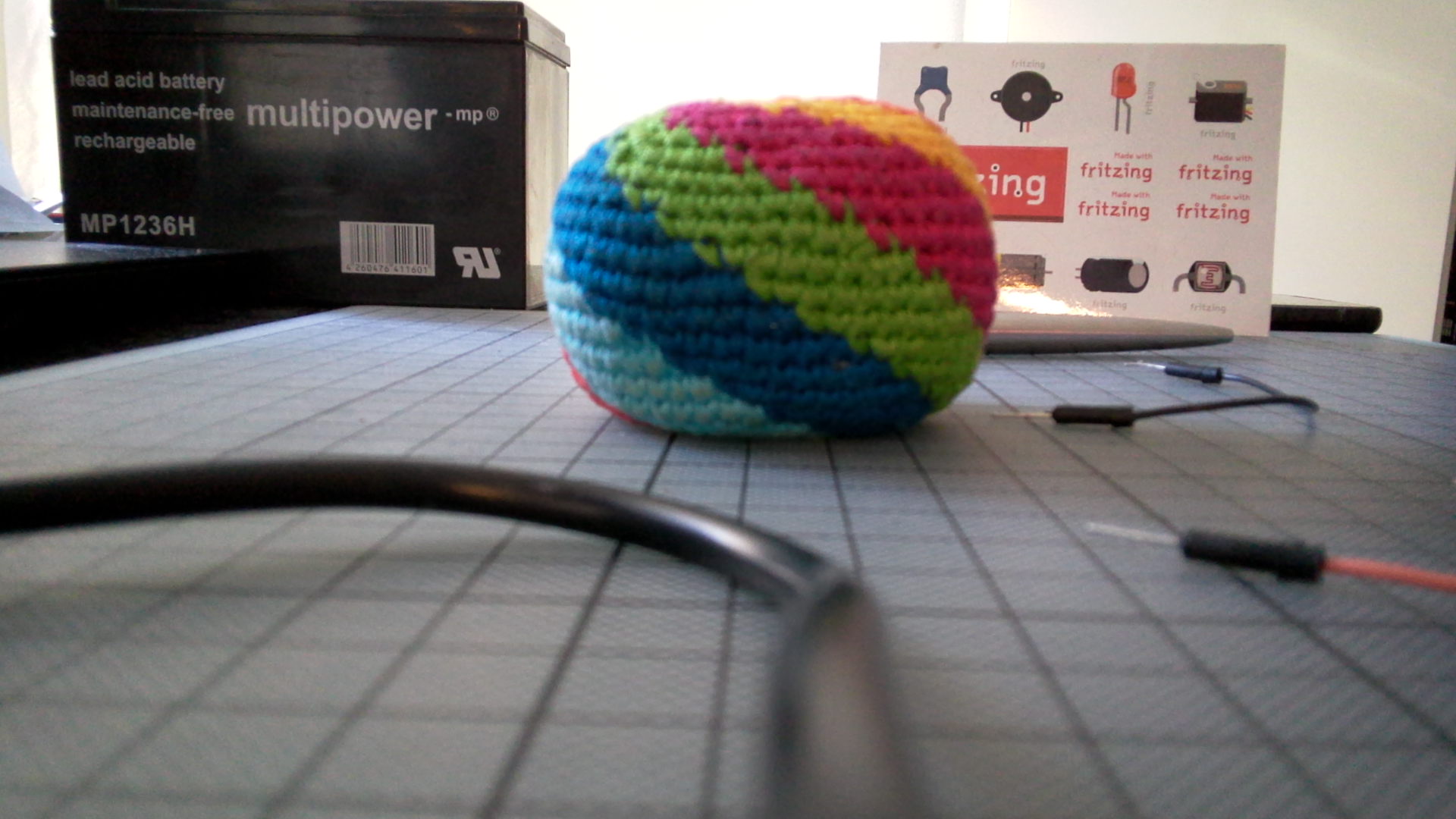
Connect to the board with minicom, and call ‘camera 0’. This will show images from the camera on our display. Even though we have reduced the video signal to 2MHz, we get quite a fluent update rate.
Since we are filming a 320x240 display, the video can not represent the capabilities of the camera. Here is a picture directly recorded with the board:
Other examples
There are many more example applications.
Zmodem
With the zmodem driver and minicom, it is easy to transfer files from the board to your PC.
GPS
Show your coordinates. The GPS demo needs a few minutes for the first fix. This is normal. To shorten the time, you need assisted GPS or you have to load ephemeral data. Maybe the GPS chip can already cache that data? We didn’t try.
TensorFlow
TensorFlow lite should allow some cool projects in connection with the camera. We didn’t get to try this one yet.
Do you have any ideas for the board? Have you already build any projects? We are looking forward to your comments in the forum.